44. Appendix 3 – Network Integration Guide
This appendix describes how to configure the network for RTBH and traffic scrubbing:
● The network configuration for RTBH (blackhole routing) is covered in the Remotely Triggered Black Hole section● The network configuration for traffic diversion and re-injection is covered in the Traffic Diversion & Forwarding section
Other topics related to the integration of Wanguard in the network are covered in different chapters:
● The most common deployment scenarios for the mitigation server are listed in the Choosing a Method of DDoS Mitigation chapter● The installation steps for Quagga, FRR, and ExaBGP are listed in the Components » BGP Connector chapter● The configuration of routers to export Netflow, sFlow, or IPFIX data towards Flow Sensor is covered in Appendix 2 – Configuring Flow Export
Note
The information provided here regarding router configurations is for informational purposes only. Please refer to the appropriate router user guides for more detailed and up-to-date information.
44.1. Remotely Triggered Black Hole
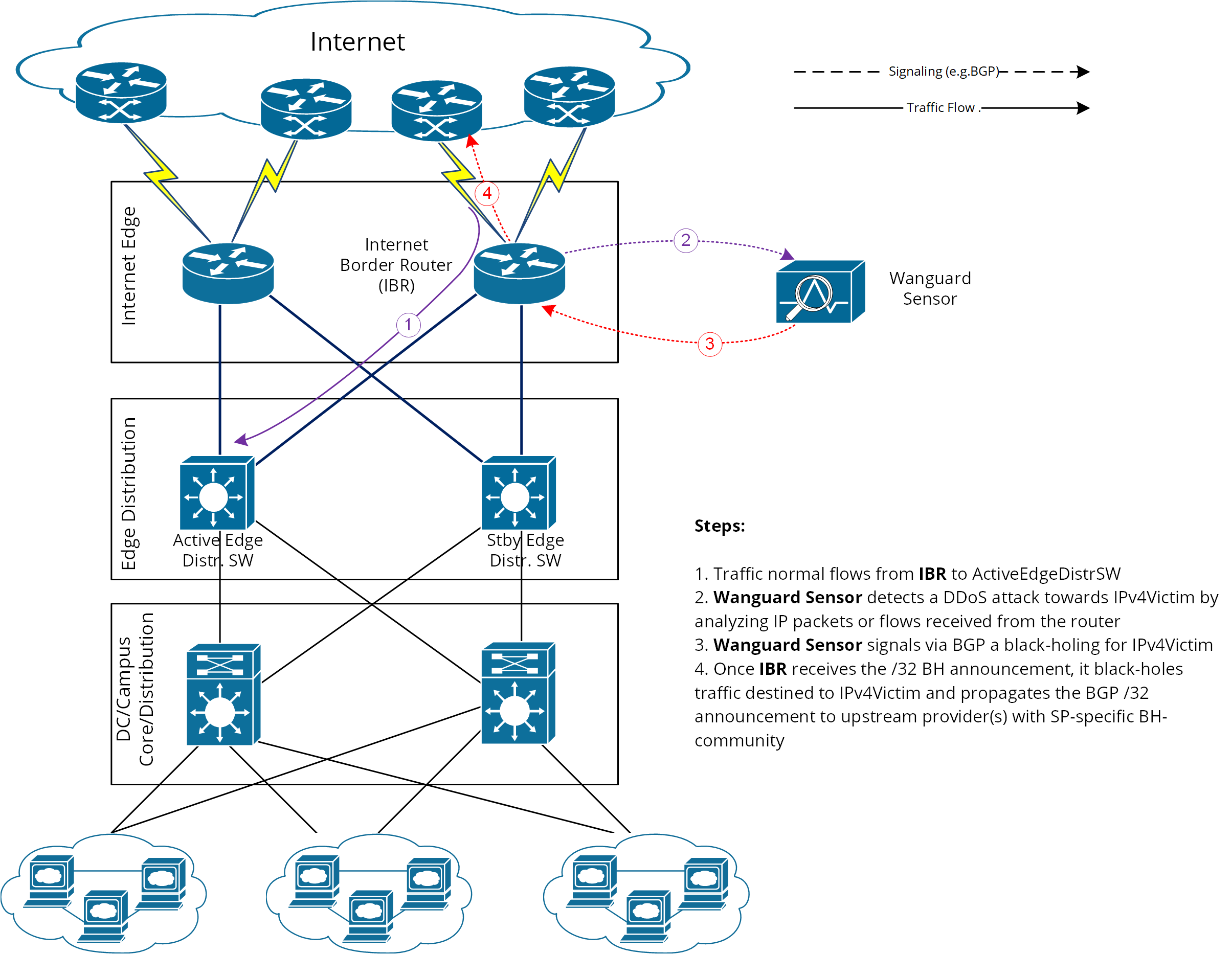
In this setup, Wanguard Sensor plays the role of Trigger. After an attack is detected, it signals the IBR (Internet Border Router) via BGP that all traffic destined to IPv4-Victim has to be dropped. In more detail:
● Wanguard Sensor advertises via BGP an IPv4-Victim/32 prefix with a specific community to be identified as a Black Hole announcement● The IBR receives the announcement and it inserts the route in its routing table as IPv4-Victim/32 with next-hop Null0● Furthermore, the IBR advertises this route to its upstream providers (ISPs), changing at the same time the community used for internal purposes to a community that is relevant to the correspondent ISP
The principle of DDoS mitigation using black hole BGP advertisements is to propagate the BH-prefix from the destination of the attack as close as possible to the source. Most ISPs have defined a public community, based on which their IBRs take the decision to black hole the traffic destined to the victim by routing it to Null0. Unlike the redirect announcements, the black-holing announcements have to be advertised to upstream ISPs.
In order to black hole the attack on the upstream provider, the black hole route must be tagged/marked with an appropriate BGP standard community. This community is provider-specific and has to be requested by each customer of the provider, or it might be found on IRR ASN details (e.g., RIPE, APNIC, ARIN, etc.).
On IBR there shall be a routing-policy applied to the to-ISP-BGP neighbor (export-direction) which shall rewrite the internal BH-community to appropriate ISP’s BH-community.
From a BGP configuration point of view, the Wanguard Sensor’s configuration is quite similar to Wanguard Filter’s BGP configuration listed in the Quagga Installation section, having one exception regarding the BGP community that will be used to mark black hole routes. Considering this, only the IBR’s configuration will be further detailed.
44.1.1. IBR BGP Session with Wanguard Sensor – Cisco Router BGP Configuration
r7500(config)# ip bgp-community new-format
r7500(config)# ip community-list <Wanguard-Sensor-community-name> permit <BH-community> → e.g., 65000:66
r7500(config)# route-map Wanguard-Filter-in permit 10
r7500(config-route-map)# match community <Wanguard-Sensor-community-name>
r7500(config-route-map)# set local-preference 200 → it will assure a higher priority against redirect-route
r7500(config-route-map)# set ip next-hop 192.168.255.255 → this target-IP must not be used on your network
r7500(config-route-map)# exit
r7500(config)# route-map Wanguard-Sensor-out deny 10
r7500(config-route-map)# exit
r7500(config)# ip route 192.168.255.255 255.255.255.255 Null0 → BH route for target-IP
r7500(config)# router bgp <Router-AS-number>
r7500(config-router)# bgp log-neighbor-changes
r7500(config-router)# neighbor <Wanguard-Sensor-IP-address> remote-as <Wanguard-Sensor-AS-number>
r7500(config-router)# neighbor <Wanguard-Sensor-IP-address> description <description>
r7500(config-router)# neighbor <Wanguard-Sensor-IP-address> soft-reconfiguration-inbound
r7500(config-router)# neighbor <Wanguard-Sensor-IP-address> route-map Wanguard-Sensor-out out
r7500(config-router)# neighbor <Wanguard-Sensor-IP-address> route-map Wanguard-Sensor-in in
r7500(config-router)# no synchronization
r7500(config-router)# exit
44.1.2. BGP Session with Two ISPs – Cisco Router BGP Configuration
r7500(config)# route-map IBR-ISP1-out permit 5 → assumes that additional entries are defined and allow customer-routes
r7500(config-route-map)# match community <Wanguard-Sensor-community-name>
r7500(config-route-map)# set community <ISP1-BH-Community> → e.g.111:9999
r7500(config-route-map)# exit
r7500(config)# route-map IBR-ISP2-out permit 5 → assumes that additional entries are defined and allow customer-routes
r7500(config-route-map)# match community <Wanguard-Sensor-community-name>
r7500(config-route-map)# set community <ISP1-BH-Community> → e.g.222:9999
r7500(config-route-map)# exit
r7500(config)# router bgp <Router-AS-number>
r7500(config-router)# neighbor <IPS1-IP-address> remote-as <ISP1-AS-number>
r7500(config-router)# neighbor <IPS1-IP-address> route-map IBR-ISP1-out out
r7500(config-router)# neighbor <IPS2-IP-address> remote-as <ISP2-AS-number>
r7500(config-router)# neighbor <IPS2-IP-address> route-map IBR-ISP2-out out
r7500(config-router)# no synchronization
r7500(config-router)# exit
When multiple ISPs and IBRs exist, it makes sense to have different BH communities, one for each IBR. In this way you may isolate the source of the attack so that the whole traffic directed to the victim would not be black-holed.
44.2. Interaction between RTBH and Traffic Diversion
This is the case when:
1. Wanguard Filter advertises redirect BGP route to IBR (initially)2. Wanguard Sensor advertises a black hole BGP route to IBR (afterward)
The priority shall be on the black hole advertisement rather than on redirect. This can be achieved easily by using a routing-policy that sets a higher priority on black hole route (e.g., set Local-Preference at 200 for BH-route).
The direction and place where BGP routing-policy has to be implemented are strongly dependent on:
● What role plays on the network the Wanguard Sensor’s peer-router (e.g., IBR, Route-Reflector, etc.)● Type of BGP relation between Wanguard Sensor and the peer-router (e.g., iBGP or eBGP)
In order to distinguish between a black hole and a redirect announcement, it is recommended to use different BGP communities on each type of announcement.
The action shall be like on the table below:
Type of BGP announcement (community) |
Route to (next-hop) |
Propagated to ISP |
Redirect (e.g., 65000:99) |
Wanguard Filter |
No |
Black Hole (e.g., 65000:66) |
Null0 |
Yes |
Table 1 – BGP Communities and actions
In the particular case when the peer-router of Wanguard Sensor is the Route-Reflector, then the black hole action still has to be implemented on IBR. To achieve this, the above sample router configuration has to be adapted and applied to IBR BGP-import policy in relation to the Route-Reflector. No action has to be implemented on RR; its purpose is route-signaling rather than routing traffic.
44.3. Traffic Diversion & Forwarding
When the Side Filtering (also known as Out-of-line Filtering) solution is deployed, then the following two major operations have to be considered:
1. Traffic diversion – how the traffic for a certain destination (IP-Victim) is diverted from network to the mitigation server2. Traffic forwarding or Re-injection – how the cleaned traffic is put back on network to be routed/forwarded towards its destination (IP-Victim)
This method relies on a basic routing principle implemented on all routers according to which a router selects the path with the longest prefix match present on routing table (also known as the “most specific” entry from routing table).
BGP has been chosen as routing protocol to inject/advertise the most specific redirect-prefix (e.g., /32 for IPv4, /128 for IPv6) towards IBR (Internet Border Router). The IBR is the router that assures routing between ISP and the internal network (customer network).
To simplify, we will consider an IPv4-Victim. In this case, Wanguard Filter sends a BGP routing update towards IBR for IPv4-Victim/32 with a next-hop to itself, forcing the IBR to choose the path to IPv4-Victim via Wanguard Filter. The main condition for this to work is to have the redirect announcement to be the best from BGP election process and from Routing-Table Manager (RTM).
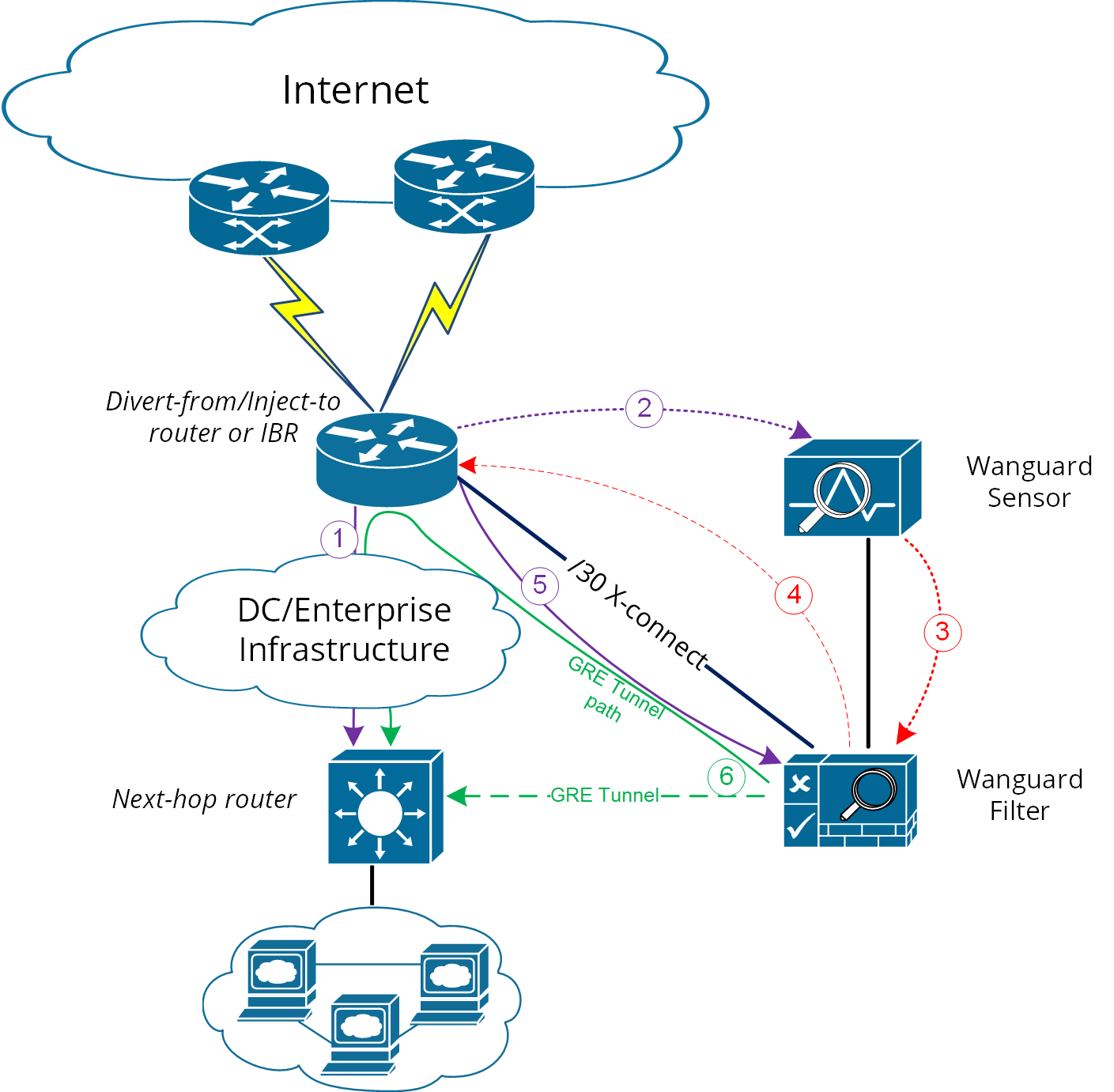
Please refer to the following logical diagram that describes the high-level process of detection-diversion-cleaning and re-injection. The following terminology is used:
● Divert-from router – Router from which the traffic initially intended for the victim is diverted towards Wanguard Filter. This router has to receive a redirect-prefix via BGP● Inject-to router – Router where Wanguard Filter will forward the cleaned traffic towards the attacked destinations (IP-Victims)● Next-hop router – Router that is usually the next-hop to the destinations according to the routing-table on the Divert-from router, before traffic diversion is activated● Wanguard Filter – In this chapter, the term generally refers to the system running Packet Filter, Flow Filter or Filter Cluster. Depending on configuration, the traffic forwarding/routing process is performed either by the Linux kernel or by DPDK
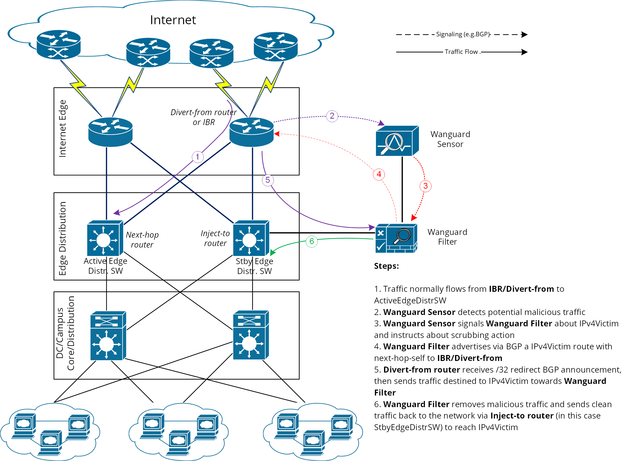
Figure-1. Logical Diagram for an Enterprise Network – how traffic diversion works
From a configuration point of view, the following steps have to be performed:
1. Configure traffic-diversion using BGP as the signaling method2. Configure an appropriate clean traffic-injection method to send clean traffic back on the network to be forwarded towards the victim
44.3.1. BGP Configuration Guideline
The guideline provided in this section applies to the BGP configuration of any router from which Wanguard Filter diverts traffic.
To simplify, the following examples are provided using eBGP (external BGPv4). This solution is not limited to eBGP, iBGP may be considered as well, depending on the existing network setup, case in which the “set nexthop-self” feature might be required.
The steps below have to be followed:
1. Configure the Wanguard Filter’s bgpd with an easily recognizable autonomous system number. This can be a private ASN for eBGP (e.g., 64512-65534) or your own public ASN in case you are using iBGP. Bgpd sends routing information only when it diverts traffic. This route appears in the router’s routing tables. Using a recognizable value allows you to easily identify the redirect-prefixes in the router’s routing tables.2. Configure additional precautionary measures to prevent any undesirable routing behavior:a. Configure Wanguard Filter’s bgpd not to accept any prefix/advertisements from Divert-from routerb. Configure Divert-from router not to advertise any prefix towards Wanguard Filterc. Configure Divert-from router to accept only redirect-prefixes from Wanguard Filter (e.g., /32 prefixes)d. Configure Wanguard Filter’s bgpd to advertise redirect-prefixes with the well-known community no-advertise – this would prevent redirect-prefixes/announcements from propagating to other peers through BGP. The no-export community might be used if the redirect-prefix has to be advertised to additional routers, or Route-Reflectors are used in-between Wanguard Filter’s bgpd and Divert-from router. Both communities will prevent BGP-redirect-announcements from being advertised towards upstream providers. However, a good practice is to mark this announcement with a dedicated BGP community to distinguish between redirect and black hole announcements.3. To ease the troubleshooting process, you may consider the soft-reconfiguration inbound command on Divert-from router during the setup procedures.
44.3.2. Cisco Router BGP Configuration
This section describes the router’s BGP configuration used when configuring traffic diversion. The syntax of the commands is taken from the BGP configuration of a Cisco router. The following configuration steps show the commands used to configure BGP on a 72xx Cisco router:
r7200(config)# ip bgp-community new-format
r7200(config)# ip community-list standard <Wanguard-Filter-community-name> permit no-advertise
r7200(config)# ip community-list standard <Wanguard-Filter-community-name> permit <Wanguard- Filter-community>
r7200(config)# route-map Wanguard-Filter-in permit 10
r7200(config-route-map)# match community <Wanguard-Filter-community-name> exact
r7200(config-route-map)# exit
r7200(config)# route-map Wanguard-Filter-out deny 10
r7200(config-route-map)# exit
r7200(config)# router bgp <Router-AS-number>
r7200(config-router)# bgp log-neighbor-changes
r7200(config-router)# neighbor <Wanguard-Filter-IP-address> remote-as <Wanguard-Filter-ASn>
r7200(config-router)# neighbor <Wanguard-Filter-IP-address> description <description>
r7200(config-router)# neighbor <Wanguard-Filter-IP-address> soft-reconfiguration-inbound
r7200(config-router)# neighbor <Wanguard-Filter-IP-address> route-map Wanguard-Filter-out out
r7200(config-router)# neighbor <Wanguard-Filter-IP-address> route-map Wanguard-Filter-in in
r7200(config-router)# exit
To display the router configuration, enter the show running-config command from the router global command level. In the following example, the router’s AS number is 1000 and the BGPd AS number is 64000. The following partial output is displayed:
r7200# show running-config
... skipped ...
router bgp 1000
bgp log-neighbor-changes
neighbor 192.168.1.100 remote-as 64000
neighbor 192.168.1.100 description Wanguard Filter server
neighbor 192.168.1.100 soft-reconfiguration inbound
neighbor 192.168.1.100 route-map Wanguard-Filter-out out
neighbor 192.168.1.100 route-map Wanguard-Filter-in in
no synchronization
!
ip bgp community new-format
ip community-list expanded Wanguard-Filter permit no-advertise
ip community-list expanded Wanguard-Filter permit <Wanguard-Filter-community>
!
route-map Wanguard-Filter-in permit 10
      match community Wanguard-Filter exact match
!
route-map Wanguard-Filter-out deny 10
!
... skipped ...
44.3.3. Juniper BGP Configuration
To get ExaBGP to work with Juniper to divert traffic via Flowspec, the BGP neighbor needs to accept legacy-redirect-ip-action:
junos> show configuration protocols bgp group WANGUARD neighbor X.X.X.X family inet flow
prefix-limit {
 maximum 50;
}
no-validate NO-VALIDATE;
legacy-redirect-ip-action {
 receive;
}
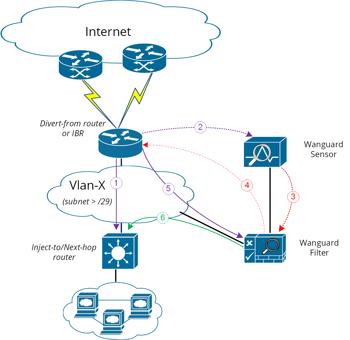
44.3.4. Layer 2 Forwarding Method
The following characteristics will describe this option:
● Wanguard Filter, Divert-from router, and Next-hop router are on the same network or VLAN sharing the same subnet● Divert-from and Inject-to routers are two different devices● Next-hop and Inject-to routers are the same device
While the above solution assumes one Divert-from and one Inject-to router, a couple of variations may be considered starting from this option:
a) Multiple Divert-from routersb) Multiple Inject-to routersc) Combination of above and/or multiple VLANs in between Divert-from and Inject-to routers
Considering the last scenario, the Wanguard Filter has to be connected to each VLAN and have static routes for each destination via the Inject-to/Next-hop routers.
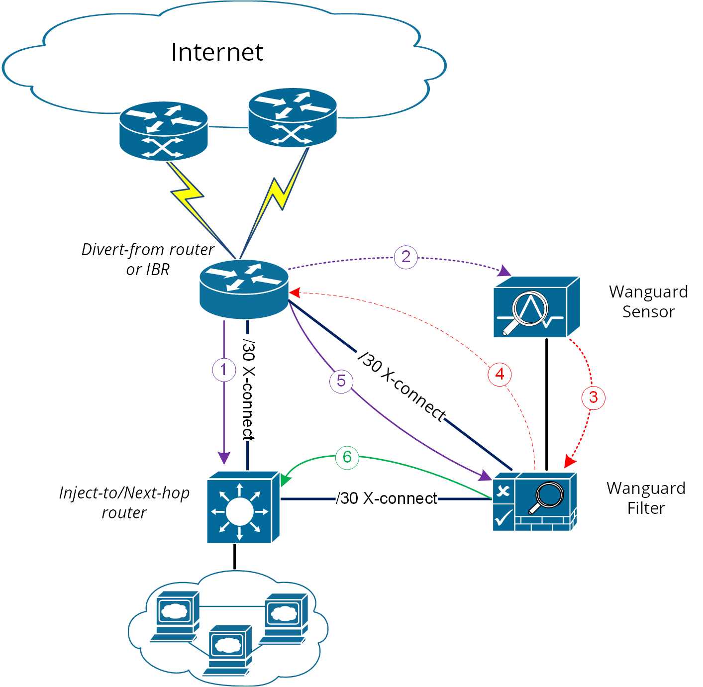
When the VLAN/LAN cannot be extended also to include Wanguard Filter on it, then a dedicated point-to-point connection might be considered between (Wanguard Filter and Divert-from) or (Wanguard Filter and Inject-to/Next-hop)
Note
Any special Layer 2 configuration on interfaces, such as bonding or VLAN-tagging, might impact the scrubbing/forwarding performance of Packet Filter. Some hardware offloads provided by the NIC might also be bypassed.
44.3.5. Layer 3 Forwarding Method
The following characteristics will describe this option:
1. Divert-from and Inject-to routers are the same device – referred in this case as “the router”2. Depending on Next-hop router’s role we may have following sub-options:a) Next-hop router is on a dedicated device but is not directly connected to Wanguard Filterb) Next-hop router is on the same device as Diver-from/Inject-to routers
In scenario 2a, a routing loop issue may occur between Divert-from/Inject-to router and Wanguard Filter:
● Wanguard Filter sends a BGP redirect announcement to Divert-from router (e.g., a /32 prefix route)● Divert-from router will send all traffic for that Victim-IP to Wanguard Filter● Wanguard Filter cleans the traffic and returns the cleaned traffic to the same router – Inject-to/Divert-from● The Inject-to router has the redirect route /32 in its routing table and will send back the clean-traffic towards Wanguard Filter, resulting a routing loop
There are a couple of solutions to overcome this issue (these are suggestions, and the best solution shall not be limited to these):
1. Using GRE (Generic Routing Encapsulation) or any L3-tunneling between Wanguard Filter and Next-hop router – in this case, routing loop is avoided by pushing clean traffic over the GRE-tunnel to Next-hop router through Divert-from/Inject-to router, bypassing in this way the /32 diversion-route from Divert-from/Inject-to:
2. Using PBR (Policy Base Routing) to override the normal routing decision from Divert-from/Inject-to router:
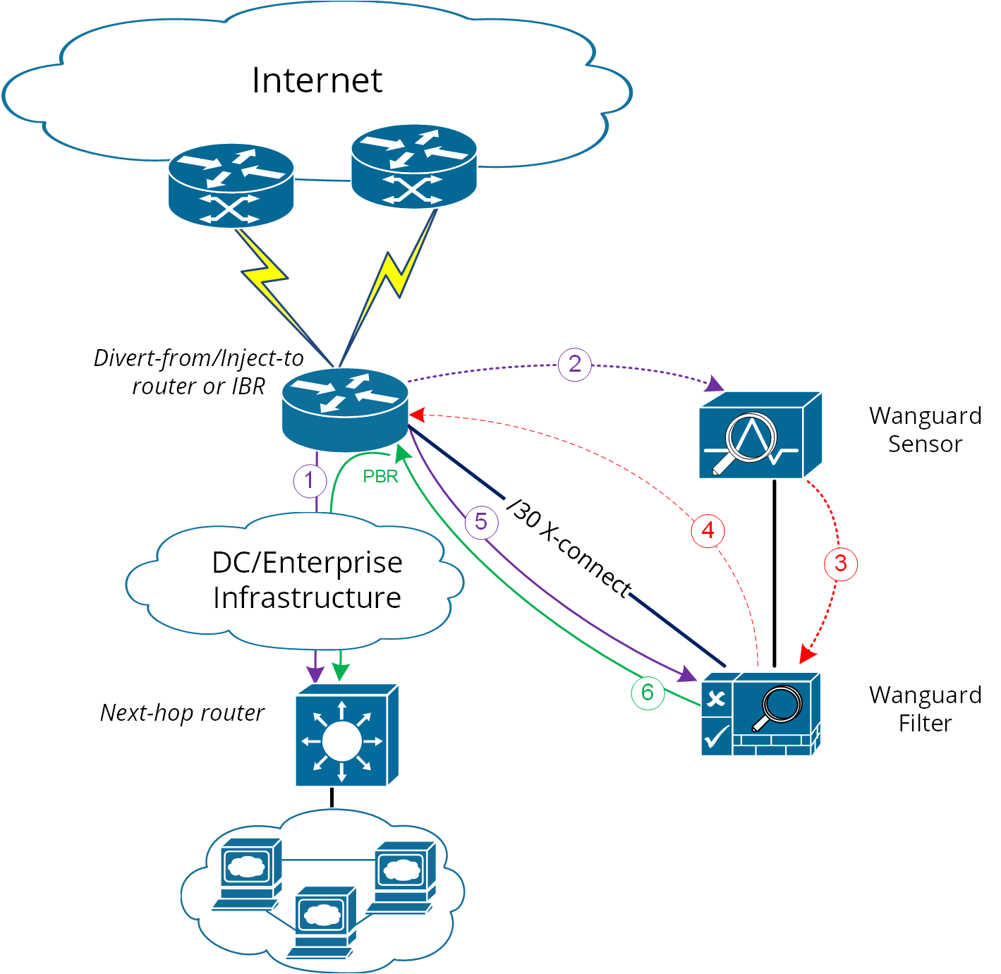
Warning
PBR may impact router performance! Depending on platform type, some optimizations may exist, but by default PBR relays on packet-by-packet processing (process-switching) which have a significant impact on router’s CPU.
In case multiple Next-hop routers exist, then the following have to be considered too:
● Multiple GRE tunnels have to be deployed, and static routes at Wanguard Filter level have to be considered, or● Multiple entries on PBR matching each zone, depending on which option is chosen
Please refer to the below router configuration samples for both GRE and PBR options:
1. The GRE method (using Cisco CLI) – configuration from Next-hop router:r7200(config)# interface Tunnel 1 r7200(config-if)# ip address <X.X.X.X> 255.255.255.252 r7200(config-if)# ip mtu 1500 r7200(config-if)# ip tcp adjust-mss 1456 r7200(config-if)# tunnel source <Y.Y.Y.Y> → where Y.Y.Y.Y is the IP from Next-hop router r7200(config-if)# tunnel destination <Z.Z.Z.Z> → where Z.Z.Z.Z is the IP from Wanguard FilterNotes:• source IP and destination IP have to be reachable• default tunneling encapsulation is GRE• routing of tunnel-destination must be assured (e.g., using static routes)• Filter will have X.X.X.X-1 IP on its Tunnel interface• If transport between Wanguard Filter and Next-hop router supports jumbo frames, then adjust MTUs accordingly in order to avoid additional packet fragmentation and implicitly performance degradation2. The PBR method (using Cisco CLI):r7200(config)#ip access-list standard Wanguard-Filter-IPScope r7200(config-std-acl)#permit A.A.A.A/BB → multiple entries may exists r7200(config-std-acl)#exit r7200(config)#route-map Wanguard-Filter-PBR permit 10 r7200(config-route-map)# match ip address Wanguard-Filter-IPScope r7200(config-route-map)# set ip next-hop <C.C.C.C> → where C.C.C.C is the IP of Next-hop router which is direct connected to Divert-from router r7200(config-route-map)#exit r7200(config)#interface GigabitEthernet 0/0 r7200(config-if)#ip policy route-map Wanguard-Filter-PBR r7200(config-if)#exit r7200(config)#
On scenario 2b when only one device has all three roles: Divert-from, Inject-to, and Next-hop – neither of the above options can be considered. PBR might be considered if a “set interface” configuration may take traffic and put it on the right Layer 2 path to its destination; since this depends on the type of platform used for routing, this would have limited applicability and will not be treated further more.
For scenario 2b a much more elaborated solution has to be considered. The main idea is to separate virtually the routing domain used by Divert-from and Inject-to/Next-hop router – falling in this way somehow on Layer 2 Forwarding Method:
● Use VRF-Lite by defining two VRF’s:• one for “outside” where Divert-from router is (and also its BGP peering with upstream providers and Wanguard Filter)• and another one for “inside” where Inject-to/Next-hop router is● Wanguard Filter must have two Layer 3 interfaces/sub-interface:• one in VRF-outside• one in VRF-inside● Like on Layer 2 Forwarding Method, static routes have to be defined on Wanguard Filter towards subnets destinations● In order to assure normal routing between these two VRF’s, MPBGP have to be activated on “the router”; no MPBGP neighbor have to be defined● On VRF’s definitions special policies for import/export Route-Targets(RT) have to be defined in the following manner:• e.g., mark outside routes with RT 65000:100 and inside routes RT 65000:200• on VRF-outside:◦ Import the routes having outside-RT (e.g., 65000:100) and also inside-RT (e.g., 65000:200)◦ Export routes with outside-RT – excepting the redirect/diversion routes• on VRF-inside:◦ Import the routes having inside-RT and specific routes having outside-RT: the default -route and/ or all other outside routes excepting the routes for diversion learned from Filter◦ Export routes with inside-RT
In this way, the inside routing table will not know about the /32 redirect prefix and will forward/route traffic normally.
For a better understanding please refer to Figure-6 and configuration on “router” using Cisco-CLI as an example:
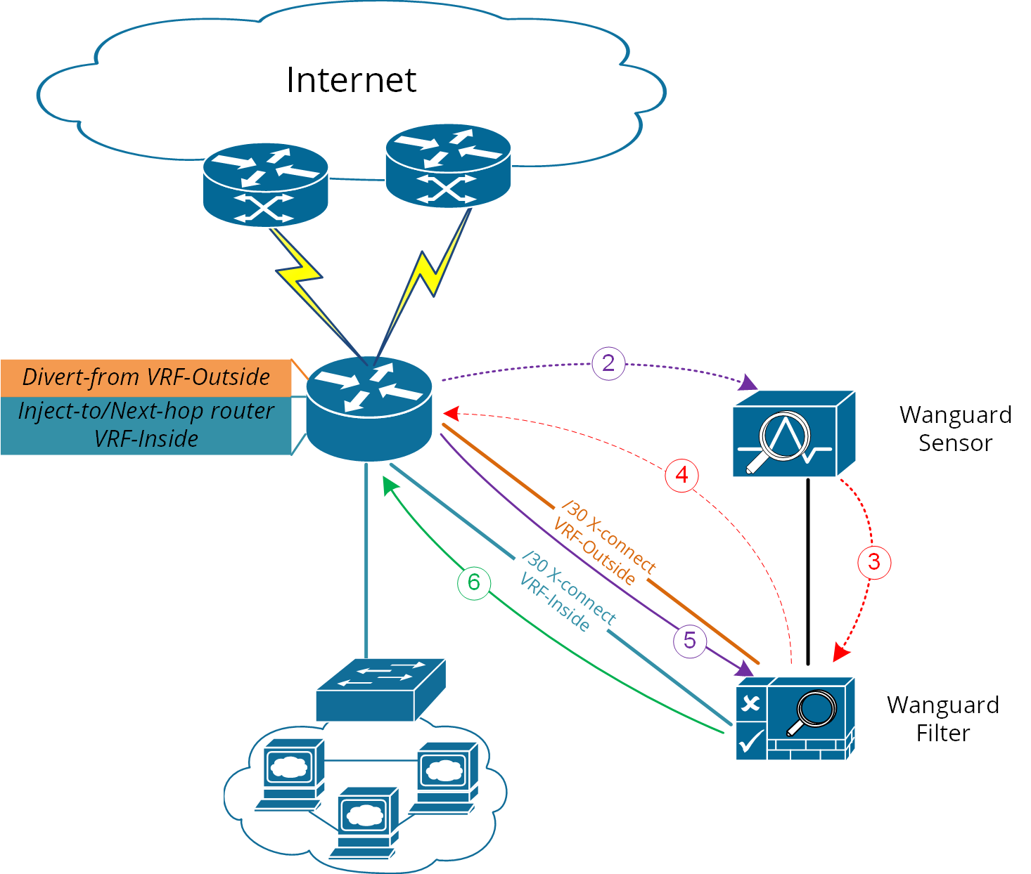
Figure-6. Logical Diagram Layer 3 Forwarding using VRF-Lite (* same steps as per Figure-1)
r7200(config)#ip extcommunity-list standard VRF-Inside permit rt 65000:200
r7200(config)#route-map VRF-Inside-Import deny 10
r7200(config-route-map)#match community Wanguard-Filter → The Wanguard-Filter community has  been already configured above; this will deny redirect-routes
r7200(config-route-map)#exit
r7200(config)#route-map VRF-Inside-Import permit 20 → This will allow any other routes
r7200(config-route-map)#exit
r7200(config)#
r7200(config)#ip vrf Outside
r7200(config-vrf)#rd 65000:100
r7200(config-vrf)#route-target import 65000:100
r7200(config-vrf)#route-target import 65000:200
r7200(config-vrf)#route-target export 65000:100
r7200(config-vrf)#exit
r7200(config)#
r7200(config)#ip vrf Inside
r7200(config-vrf)#rd 65000:200
r7200(config-vrf)#route-target import 65000:100
r7200(config-vrf)#route-target import 65000:200
r7200(config-vrf)#import map VRF-Inside-Import
r7200(config-vrf)#route-target export 65000:200
r7200(config-vrf)#exit
r7200(config)#
r7200(config)# interface Loopback0 → This is needed to have a BGP router-id (any existing Loopback from global can be reused)
r7200(config-if)# ip address <Z.Z.Z.Z/32>
r7200(config-if)#no shut
r7200(config-if)#exit
r7200(config)#
r7200(config)# interface <to Upstream Provider>
r7200(config-if)#ip vrf forwarding Outside → Warning! This will remove IP address from interface/IP-address has to be reconfigured again
r7200(config-if)#exit
r7200(config)#
r7200(config)# interface <to Filter off-ramp interface>
r7200(config-if)#ip vrf forwarding Outside → Warning! This will remove IP address from interface/IP-address has to be reconfigured again
r7200(config-if)#exit
r7200(config)#
r7200(config)# interface <to Filter on-ramp interface>
r7200(config-if)#ip vrf forwarding Inside → Warning! This will remove IP address from interface/IP-address has to be reconfigured again
r7200(config-if)#exit
r7200(config)#
r7200(config)# interface <to Inject-to/Next-hop>
r7200(config-if)#ip vrf forwarding Inside → Warning! This will remove IP address from interface/IP-address has to be reconfigured again
r7200(config-if)#exit
r7200(config)#
r7200(config)#router bgp 65000 → You may use your ASN instead of 65000
r7200(config-router)# no synchronization
r7200(config-router)#bgp log-neighbor-changes
r7200(config-router)#no auto-summary
r7200(config-router)#address-family vpnv4
r7200(config-router-af)# no synchronization
r7200(config-router-af)#exit-address-family
r7200(config-router)# address-family ipv4 vrf Inside
r7200(config-router-af)# no synchronization
r7200(config-router-af)# redistribute connected
r7200(config-router-af)# redistribute <other IGP/static if needed>
r7200(config-router-af)#exit-address-family
r7200(config-router)# address-family ipv4 vrf Outside
r7200(config-router-af)# no synchronization
r7200(config-router-af)# redistribute connected
r7200(config-router-af)# redistribute <other IGP/static if needed>
r7200(config-router-af)#exit-address-family
r7200(config-router)#exit
r7200(config)#