38. Appendix 1 – DPDK Configuration

Warning

The DPDK port is currently in a “Technological Preview” state. The support is very limited and the software is not deemed as stable enough to use it in production!

Wanguard 8.0 supports DPDK version 19.11.2 on Intel microarchitectures starting with Sandy Bridge (Ivy Bridge, Haswell, Broadwell, Skylake, etc.). The code is currently optimized for Broadwell. NICs that need special drivers for DPDK (e.g. Mellanox) might not be supported. For other limitations of DPDK please consult the table from the Choosing a Method of DDoS Mitigation chapter.

To use DPDK 19.11.2, follow the installation guide from http://www.dpdk.org and allocate at least 8 hugepages each with 1 GB page size. There are several BIOS optimization settings required, as well as a number of kernel parameters that increase the performance of the server. It may be possible to purchase preconfigured appliances, already optimized for DPDK, from https://www.andrisoft.com/hardware/anti-ddos-appliance.

38.1. Application Workflow

The architecture of the application is similar to the one presented in the following diagram which illustrates a specific case of two I/O RX and two I/O TX lcores (logical CPU cores) off-loading the packet Input/Output overhead incurred by four NIC ports, with each I/O lcore handling RX/TX for two NIC ports. The RX lcores are dispatching the packets toward two Distributor cores which are distributing them to six Worker lcores.

10000000000018450000099F904BCF07F884E1B4_png

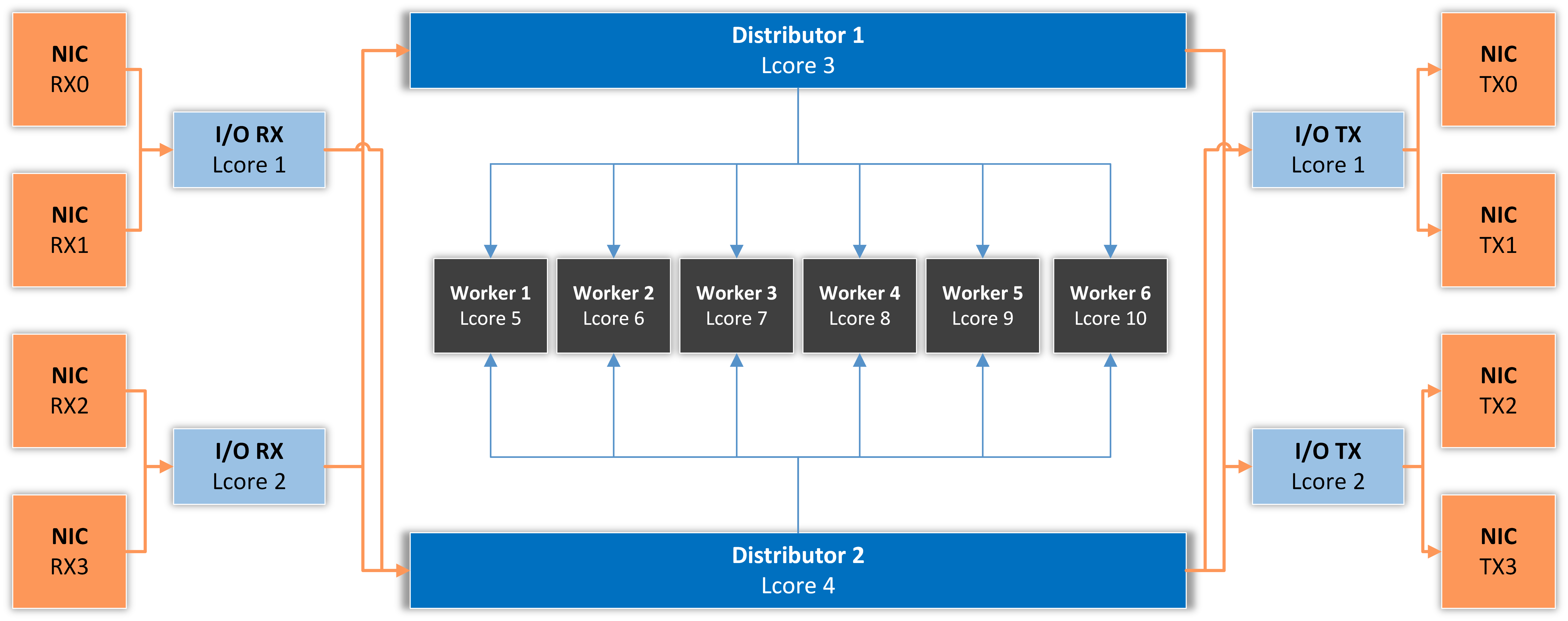
I/O RX Lcore performs packet RX from the assigned NIC RX rings and then dispatches the received packets to one or more distributor lcores using RSS or a round-robin algorithm.

Distributor Lcore reads packets from one or more I/O RX lcores, extracts packet metadata, performs the Dataplane firewall’s functionality, and dispatches packet metadata to one or more Worker lcores.

Worker Lcore performs the most heavy weight and CPU-intensive tasks such as traffic analysis and attack detection.

I/O TX Lcore performs packet TX for a predefined set of NIC ports. The packets are forwarded in batches of minimum 4, so the latency will be very high (>50 ms!) if the application forwards just a few packets per second. On thousands of packets/s the latency falls well under 1 millisecond.

The application needs to use one Master Lcore to aggregate data from the workers.

38.2. DPDK Capture Engine Options

EAL Options – See the DPDK Getting Started Guide for more information on this mandatory parameter
RX Parameters – The syntax is “(PORT,QUEUE,LCORE)..” and represents a list of NIC RX ports and queues handled by the I/O RX lcores. This parameter also implicitly defines the list of I/O RX lcores. This is a mandatory parameter
Distributor Mode – Specify the algorithm used to dispatch packets from the RX to the Distributor lcores:
Round-robin – The load is shared equally between the Distributor lcores. This is the best option when the packets are not forwarded
RSS – The packets with the same RSS value are always dispatched to the same Distributor lcore. This is the best option when packets are forwarded, mainly because it maintains the order of the packets
Custom – Select this option to be able to specify the Distributor lcore for each RX port. In this case, the RX Parameters syntax becomes “(PORT,QUEUE,LCORE,DISTRIBUTOR_LCORE_NO)..”
Distributor Lcores – Enter the lcore of the Distributor thread, or a list of lcores separated by comma. This is a mandatory parameter
Worker Lcores – The list of worker lcores. This is a mandatory parameter
Master LCORE – Set an lcore to be used exclusively for thread management purposes. The recommended value is the hyper-thread core of CPU 0 because its performance is not important. This is a mandatory parameter
Forwarding Mode – Specify the TX functionality:
Disabled – The packets are not forwarded, so the application behaves like a passive sniffer
Transparent Bridge – All Ethernet frames are forwarded without any intervention, so the application works like a transparent bridge. This is the fastest forwarding method.
IP Forwarding – The application performs several tasks for each packet. If it’s an ARP packet querying for the MAC address of one of the interfaces defined below it responds to that query. On all other packets, it rewrites the source MAC address with the output interface MAC, and it rewrites the destination MAC with the MAC address defined below. The application is not performing RFC 1812 checks and is not decreasing the TTL value. This forwarding method is necessary when the server is deployed out-of-line with traffic redirected by BGP. For latency considerations see the previous option
TX Parameters – The syntax is “(PORT,LCORE)..” and it defines a list of NIC TX ports handled by the I/O TX lcores. This parameter also implicitly defines the list of I/O TX lcores. This parameter is mandatory when the Forwarding Mode is not set to Disabled
Forwarding Table – The syntax is “(PORT_IN,PORT_OUT)..” and it defines the output interface depending on the input interface
Interface IPs – The syntax is “(PORT,IPV4)..” and it defines the IP of each port. This parameter is used when the Forwarding Mode is set to IP Forwarding but it does not ensure a true TCP/IP stack on the interface. The application will respond to ARP requests, but it’s highly recommended to set the ARP table manually on the router because the application could respond to ARP requests with a high latency due to bulk processing
Destination MACs – The syntax is “(PORT,MAC_ADDRESS)..” and it defines the gateway MAC address for each port. This option is used when the Forwarding Mode is set to IP Forwarding
Maximum Frame Size – If the network uses jumbo frames, enter the maximum frame size (usually 9000). Otherwise the default value is 1518, which captures normal Ethernet frames
IP Hash Table Size – By default, the IPs are tracked using a hash table with 524288 elements for each worker lcore, IP version and traffic direction
Int. IP Mempool Size – The default value is 70000 which means that each worker lcore pre-allocates RAM space to hold traffic information for up to 70000 IPs. The mempool is refreshed every 1 to 5 seconds, so to reach this limit all hosts must send or receive traffic during this period. The RAM space required per IP is listed in Sensor Graphs by selecting the Data Unit “IP Structure RAM”
Ext. IP Mempool Size – This mempool is used for recording traffic information for external IP addresses. The default value is 120000 per worker lcore
Ring Sizes – The accepted format is “A, B, C, D”:
○ A = The size (in number of buffer descriptors) of each of the NIC RX rings read by the I/O RX lcores
○ B = The size (in number of elements) of each of the software rings used by the I/O RX lcores to send packets to worker lcores
○ C = The size (in number of elements) of each of the software rings used by the worker lcores to send packets to I/O TX lcores
○ D = The size (in number of buffer descriptors) of each of the NIC TX rings written by I/O TX lcores The default values are “1024, 1024, 1024, 1024” which are optimal for the Intel ixgbe driver. Other network controllers and/or drivers might use different values
Burst Sizes – The accepted format is “(A, B), (C, D), (E, F)”.
○ A = The I/O RX lcore read burst size from NIC RX
○ B = The I/O RX lcore write burst size to the output software rings
○ C = The worker lcore read burst size from the input software rings
○ D = The worker lcore write burst size to the output software rings
○ E = The I/O TX lcore read burst size from the input software rings
○ F = The I/O TX lcore write burst size to the NIC TX
The default values are “(144,144),(144,144),(144,144)” when Forwarding Mode is disabled, and “(8,8),(8,8), (8,8)” when Forwarding Mode is enabled. A burst size of 8 effectively means that the software will process at least 8 packets in parallel. So, on a traffic of 1 packet/s you will see a significant latency. It is not possible to use values less than 4 in DPDK 18.11 or 8 in DPDK 19.11

38.3. DPDK Configuration Example

Execute the script usertools/cpu_layout.py from the your dpdk directory to see the CPU layout of your server. The following configuration assumes this CPU layout of a 14-core Xeon processor: Core 0 [0, 14], Core 1 [1, 15], Core 2 [2, 16], Core 3 [3, 17], Core 4 [4, 18], Core 5 [5, 19], Core 6 [6, 20], Core 8 [7, 21], Core 9 [8, 22], Core 10 [9, 23], Core 11 [10, 24], Core 12 [11, 25], Core 13 [12, 26], Core 14 [13, 27].

DPDK_OPTIONS8.01_png

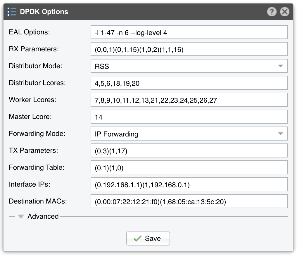
EAL Options contains the parameter “-l 1-27” which configures DPDK to use the lcores 1 to 27 (28 lcores = 14- core CPU with Hyper-threading enabled). The parameter “-n 4” configures DPDK to use 4 memory channels which is the maximum of what the reference Intel Xeon CPU (14-core Broadwell) supports.

The RX parameters configure the application to listen to the first two DPDK-enabled interfaces (0 and 1), on two NIC queues (0 and 1), and to use two CPU cores for this task (15 and 16 are the hyper-threads of cores 1 and 2).

The Distributor Mode setting ensures that the packets will be forwarded in the same order.

Three CPU cores are used for the Dataplane firewall and to distribute packets to the workers: 4, 5 and 6 (18, 19 and 20 are hyper-threads).

Seven CPU cores are used for packet analysis and attack detection: 7 to 13 (21 to 27 are hyper-threads).

The Master lcore is the hyper-thread of CPU core 0 which is used by the OS.

The TX parameters configure the application to use a single CPU core for TX. Lcore 3 sends packets over port 0, while the lcore 17 (hyper-thread of CPU core 3) sends packets over port 1.

The Forwarding Table value specifies that incoming packets on port 0 should be sent to port 1, and vice versa.

The next two parameters set the IPs and the destination MACs for both ports.