42. Appendix 1 – DPDK Configuration

Wanguard 8.3 is compatible with DPDK 23.11 running on Ubuntu 18 to 22, Debian 10 to 12, and Rocky/AlmaLinux 8 or 9. The code is currently optimized for the Broadwell microarchitecture and it runs on every Intel microarchitecture starting with Sandy Bridge (Ivy Bridge, Haswell, Broadwell, Skylake, etc.) as well as on AMD Zen processors. For other limitations of DPDK, please consult the comparison table from the Choosing a Method of DDoS Mitigation chapter.

To use DPDK 23.11, follow the installation guide from https://www.dpdk.org and allocate at least 8 hugepages, each with 1 GB page size. When building DPDK, make sure that libpcap-dev is installed, to be able to capture packet dumps. It’s also recommended to follow the BIOS optimization steps provided by DPDK.

42.1. Application Workflow

The architecture of the application is similar to the one presented in the following diagram, which illustrates a specific case of two I/O RX and two I/O TX lcores (logical CPU cores) off-loading the packet Input/Output overhead incurred by four NIC ports, with each I/O lcore handling RX/TX for two NIC ports. The RX lcores are dispatching the packets toward two Distributor cores which are distributing them to six Worker lcores.

10000000000018450000099F904BCF07F884E1B4_png

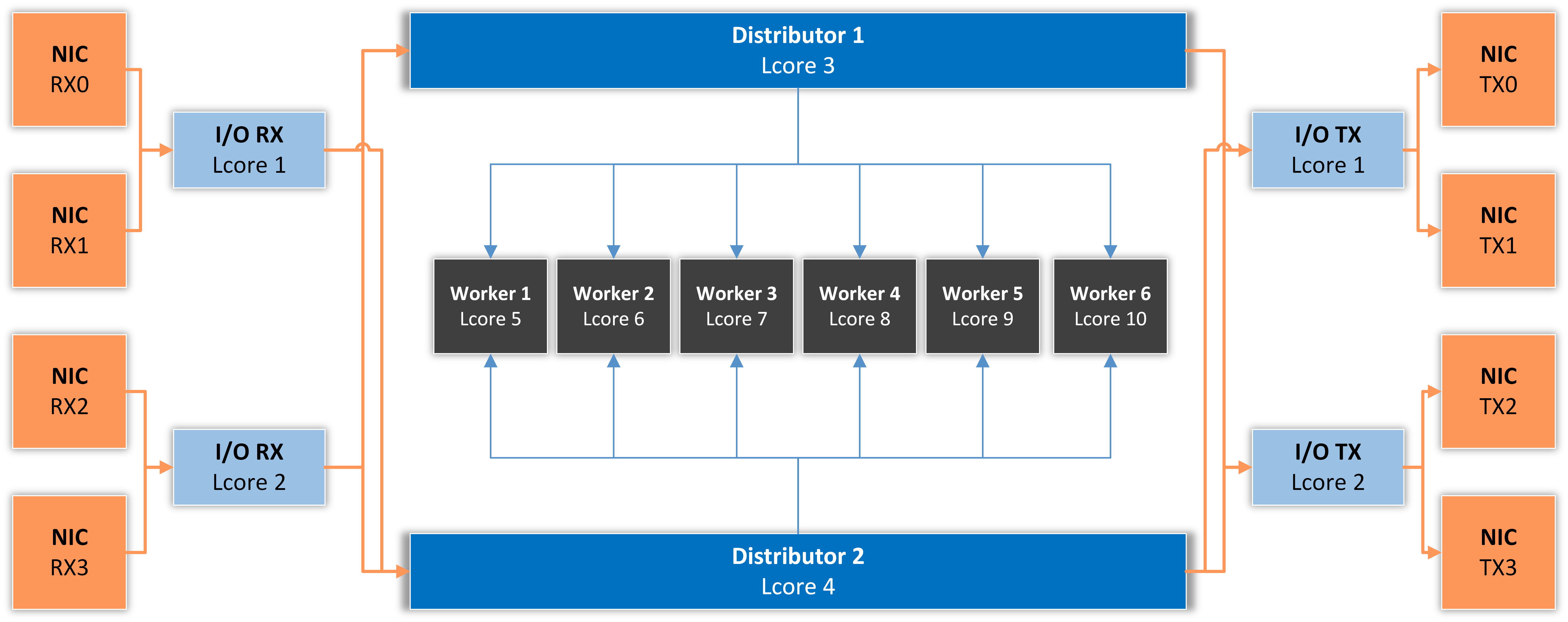
I/O RX Lcore performs packet RX from the assigned NIC RX rings and then dispatches the received packets to one or more distributor lcores using RSS or a round-robin algorithm.

Distributor Lcore reads packets from one or more I/O RX lcores, extracts packet metadata, performs the Dataplane firewall’s functionality, and dispatches packet metadata to one or more Worker lcores.

Worker Lcore performs heavy-weight and CPU-intensive tasks such as traffic analysis and attack detection.

I/O TX Lcore performs packet TX for a predefined set of NIC ports. The packets are forwarded in batches of minimum 4, so the latency will be very high (>50 ms!) if the application forwards just a few packets per second. On thousands of packets/s, the latency falls well under one millisecond.

The application needs to use one Master Lcore to aggregate data from the workers.

42.2. DPDK Capture Engine Options

DPDK Driver – Select the second option if DPDK is used with Mellanox NICs. Otherwise, select the first parameter
EAL Options – See the DPDK Getting Started Guide for more information on this mandatory parameter, or the Configuration Example listed below
RX Parameters – The syntax is “(PORT,QUEUE,LCORE)..” and represents a list of NIC RX ports and queues handled by the I/O RX lcores. This parameter also implicitly defines the list of I/O RX lcores. This is a mandatory parameter
Distributor Mode – Specify the algorithm used to dispatch packets from the RX to the Distributor lcores:
Round Robin – The load is shared equally between the Distributor lcores. This is the best option when the packets are not forwarded
Receive Side Scaling (RSS) – The packets with the same RSS value are always dispatched to the same Distributor lcore. This is the best option when packets are forwarded, mainly because it maintains the order of packets
Custom – Select this option to specify the Distributor lcore for each RX port. In this case, the RX Parameters syntax becomes “(PORT,QUEUE,LCORE,DISTRIBUTOR_LCORE_NO)..”
Distributor Lcores – Enter the lcore of the Distributor thread, or a list of lcores separated by a comma. This is a mandatory parameter
Worker Lcores – The list of worker lcores. This is a mandatory parameter
Master LCORE – Set an lcore to be used exclusively for thread management purposes. The recommended value is the hyper-thread core of CPU 0 because its performance is not important. This is a mandatory parameter
Forwarding Mode – Specify the TX functionality. Note that this feature is not recommended for production because the packet latency can be very high!
Disabled – The packets are not forwarded, so the application behaves like a passive sniffer
Transparent Bridge – All Ethernet frames are forwarded without intervention, so the application works like a transparent bridge. This is the fastest forwarding method
IP Forwarding – The application performs several tasks for each IPv4 packet (IPv6 is not supported yet!). If it’s an ARP packet querying for the MAC address of one of the interfaces defined below it responds to that query. On all other packets, it rewrites the source MAC address with the output interface MAC, and it rewrites the destination MAC with the MAC address defined below. The application is not performing RFC 1812 checks and is not decreasing the TTL value. This forwarding method is necessary when the server is deployed out-of-line with traffic redirected by BGP
TX Parameters – The syntax is “(PORT,LCORE)..” and defines a list of NIC TX ports handled by the I/O TX lcores. This parameter also implicitly defines the list of I/O TX lcores. This parameter is mandatory when the Forwarding Mode is not set to Disabled
Forwarding Table – The syntax is “(PORT_IN,PORT_OUT)..” and defines the output interface depending on the input interface
Interface IPs – The syntax is “(PORT,IPV4)..” and defines the IP of each port. This parameter is used when the Forwarding Mode is set to IP Forwarding, but it does not ensure a true TCP/IP stack on the interface. The application will respond to ARP requests, but it’s highly recommended to set the ARP table manually on the router because the application could respond to ARP requests with a high latency due to bulk processing
Destination MACs – The syntax is “(PORT,MAC_ADDRESS)..” and defines the gateway MAC address for each port. This option is used when the Forwarding Mode is set to IP Forwarding
Maximum Frame Size – If the network uses jumbo frames, enter the maximum frame size (usually 9000). Otherwise, the default value is 1518, which captures normal Ethernet frames
IP Hash Table Size – By default, the IPs are tracked using a hash table with 1048576 elements for each traffic direction, with different tables for IPv4 and IPv6
Int. IP Mempool Size – The default value is 1048576 which means that RAM is pre-allocated to hold traffic information for up to 1M internal IPs (included in IP Zone), splitted equally between worker lcores. The mempool is refreshed every 1 to 5 seconds, so to reach this limit, all hosts must send or receive traffic during this period. The RAM space required per IP is listed in Sensor Graphs by selecting the Data Unit “IP Structure RAM”
Ext. IP Mempool Size – This mempool is used for recording traffic information for external IP addresses. The default value is 1048576, splitted equally between worker lcores
Ring Sizes – The accepted format is “A, B, C, D”:
◦ A = The size (in number of buffer descriptors) of each of the NIC RX rings read by the I/O RX lcores
◦ B = The size (in number of elements) of each of the software rings used by the I/O RX lcores to send packets to worker lcores
◦ C = The size (in number of elements) of each of the software rings used by the worker lcores to send packets to I/O TX lcores
◦ D = The size (in number of buffer descriptors) of each of the NIC TX rings written by I/O TX lcores The default values are “1024, 1024, 1024, 1024” which are optimal for the Intel ixgbe driver. Other network controllers and/or drivers might use different values
Burst Sizes – The accepted format is “(A, B), (C, D), (E, F)”.
◦ A = The I/O RX lcore read burst size from NIC RX
◦ B = The I/O RX lcore write burst size to the output software rings
◦ C = The worker lcore read burst size from the input software rings
◦ D = The worker lcore write burst size to the output software rings
◦ E = The I/O TX lcore read burst size from the input software rings
◦ F = The I/O TX lcore write burst size to the NIC TX
The default values are “(144,144),(144,144),(144,144)” when Forwarding Mode is disabled, and “(8,8),(8,8),(8,8)” when Forwarding Mode is enabled. A burst size of 8 effectively means that the software will process at least 8 packets in parallel. So, on a traffic of just a few packet/s, you will notice a significant latency

42.3. DPDK Configuration Example

Execute the script usertools/cpu_layout.py from the your dpdk source directory to see the CPU layout of your server. The following configuration assumes this CPU layout of a 14-core Xeon processor: Core 0 [0, 14], Core 1 [1, 15], Core 2 [2, 16], Core 3 [3, 17], Core 4 [4, 18], Core 5 [5, 19], Core 6 [6, 20], Core 8 [7, 21], Core 9 [8, 22], Core 10 [9, 23], Core 11 [10, 24], Core 12 [11, 25], Core 13 [12, 26], Core 14 [13, 27].

DPDK_OPTIONS8.01_png

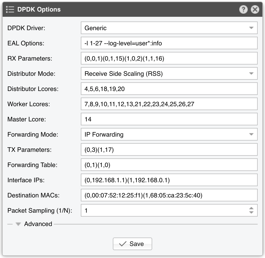
EAL Options contains the parameter “-l 1-27” which configures DPDK to use the lcores 1 to 27 (28 lcores = 14-core CPU with Hyper-threading enabled). The parameter “-n 4” configures DPDK to use 4 memory channels which is the maximum of what the reference Intel Xeon CPU (14-core Broadwell) supports. The parameter “–log-level=user*.info” activates the logging of the DPDK engine in syslog.

The RX parameters configure the application to listen to the first two DPDK-enabled interfaces (0 and 1), on two NIC queues (0 and 1), and to use two CPU cores for this task (15 and 16 are the hyper-threads of cores 1 and 2).

The Distributor Mode setting ensures that the packets will be forwarded in the same order.

Three CPU cores are used for the Dataplane firewall and to distribute packets to the workers: 4, 5 and 6 (18, 19 and 20 are hyper-threads).

Seven CPU cores are used for packet analysis and attack detection: 7 to 13 (21 to 27 are hyper-threads).

The Master lcore 14 is the hyper-thread of CPU core 0, which is the OS uses.

In this example, the DPDK Engine acts as a L3 pseudo-router in order to use an out-of-line topology via BGP, so the Forwarding Mode parameter is set to IP Forwarding.

The TX parameters configure the application to use a single CPU core for TX. Lcore 3 sends packets over port 0, while lcore 17 (hyper-thread of CPU core 3) sends packets over port 1.

The Forwarding Table value specifies that incoming packets on port 0 should be sent to port 1 and vice versa.

The Interface IPs parameter specifies that DPDK Engine should respond to ARP requests on port 0 with the IP 192.168.1.1, and to ARP requests on port 1 with the IP 192.168.0.1. So, when a router wants to forward packets to 192.168.1.1 or 192.168.0.1, the DPDK Engine responds with the MAC of interface 0 or 1. After the ARP is received by the router, it will then be able to start sending packets to the right interface.

The Destination MACs parameter specifies that the packets forwarded by port 0 will be received by a gateway that has the MAC 00:07:52:12:25:f1, and for port 1 the gateway has the MAC 68:05:ca:23:5c:40. Because the DPDK Engine does not provide an IP stack and doesn’t maintain an ARP table, the MACs of the gateways must be set manually.

Note

The distribution of lcores can be optimized by observing the performance-related statistics from Reports » Devices » Overview » Dataplane.